multishifter

casm powered utility to create gamma surfaces, UBER curves, and twisted bilayers along crystal planes.
Tutorial V: Shifting for \(\gamma\)-surfaces
In this tutorial we’ll use multishift shift to generate many slab structures that have been shifted along the \(ab\)-plane of their unit cell (glide plane).
Calculations of these structures can be used to calculate \(\gamma\)-surfaces.
Mg slab cell
We’ll start with a slab of \(\mathrm{Mg}\) with 8 atomic layers (4 unit cells tall).
This is the same slab from the mutate tutorial.
You can download it here, or create a file called mg_stack4.vasp yourself with the follwing data:
Mg stack
1.00000000
   1.59609453    2.76451683    0.00000000
  -1.59609453    2.76451683    0.00000000
   0.00000000    0.00000000   20.73607828
Mg
8
Direct
   0.66666670    0.66666670    0.18750000 Mg
   0.33333330    0.33333330    0.06250000 Mg
   0.66666670    0.66666670    0.43750000 Mg
   0.33333330    0.33333330    0.31250000 Mg
   0.66666670    0.66666670    0.68750000 Mg
   0.33333330    0.33333330    0.56250000 Mg
   0.66666670    0.66666670    0.93750000 Mg
   0.33333330    0.33333330    0.81250000 Mg
You can also create your own slab from a primitive cell using multishift stack, as explained in a previous tutorial.
Shift your slab
The shift command takes the dimensions of a grid that will be applied to the \(ab\)-plane of your slab.
Each grid point corresponds to a particular in plane shift or glide, and corresponds to a point on the \(\gamma\)-surface.
We’ll give a \(3\times3\) grid, for a total of 9 surface points.
The densities are given in the order \(a\times b\), where $a$ and $b$ are the number of divisions that should be made along the $a$ and $b$ vectors of your slab.
multishift shift --input mg_stack4.vasp --grid 3 3 --output mg_shift
Once you’ve run this command, the output directory al_shift will be created, which has the following structure:
mg_shift/
├── slab.vasp
├── record.json
├── shift__2.2
│   └── POSCAR
├── shift__2.1
│   └── POSCAR
├── shift__2.0
│   └── POSCAR
├── shift__1.2
│   └── POSCAR
├── shift__1.1
│   └── POSCAR
├── shift__1.0
│   └── POSCAR
├── shift__0.2
│   └── POSCAR
├── shift__0.1
│   └── POSCAR
└── shift__0.0
    └── POSCAR
The first file slab.vasp is simply a backup of the input structure al_stack8.vasp.
The second file record.json holds a short description for each of the generated structures, and is described in detail in a separate tutorial.
The generated structures are each saved to an idividual directory named shift__*.*, with the indexes of the grid point formatted into the directory name.
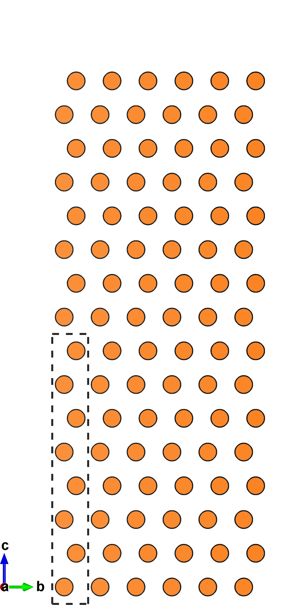
shift__0.0 corresponds to the initial unperturbed slab.
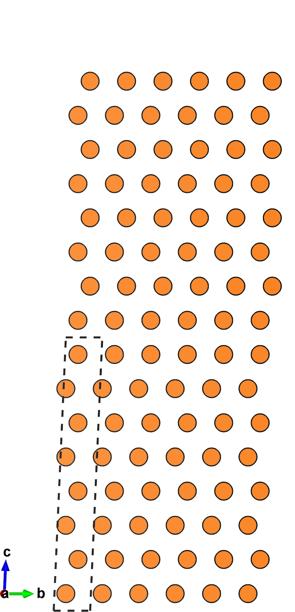
Generally speaking, for a \(N\times M\) grid, shift__n.m corresponds to an in plane shift vector \((\frac{n}{N},\frac{m}{M})\) in fractional coordinates relative to the slab \(ab\) vectors.
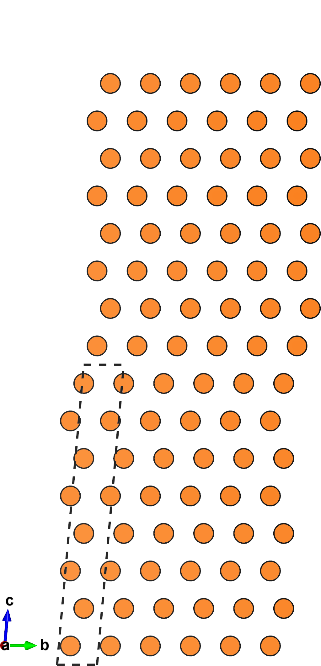
This means shift_2.2 has the slabs shifted by \((\frac{2}{3},\frac{2}{3})\), which is the same as the stacking fault we created in the mutate tutorial.
The figures below show the structures of shift__0.0, shift__1.1, and shift__2.2.
 |
 |
 |
Notice that for this \(3\times 3\) grid, the next structure that would appear in this sequence is shift__3.3.
This would be the same as shift__0.0, and so it is not outputted.
Equivalent shifts
Due to the symmetry of the crystal, enumerating all the shifted slab structures on a grid often results in symmetrically equivalent structures.
In the \(3\times 3\) \(\mathrm{Mg}\) example we looked at, shifting purely along the \(a\) vector is equivalent to shifting purely along the \(b\) vector.
Therefore, we expect shift__1.0 to be equivalent to shift__0.1.
This information is stored in record.json.
The format is explained in detail here.
For our example, we find that there are just 4 orbits of slab structures.
This means we need only calculate DFT energies for for structures to get the energies of all 9.
If we repeat the enumeratation with a \(12\times 12\) grid instead, we find there are 31 orbits, which is a lot less than the total 144 structures.
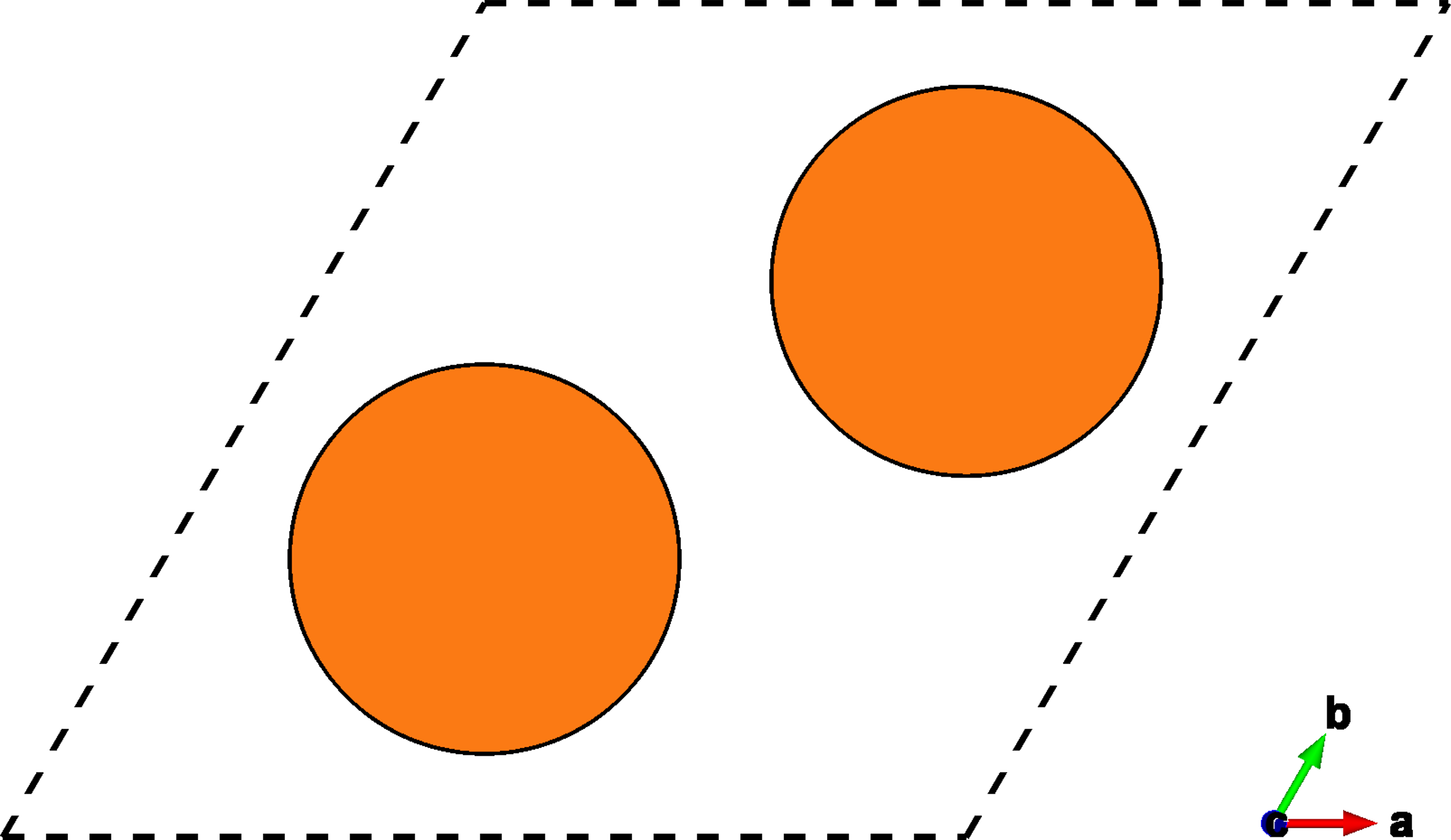
We can visualize the symmetry of the glide plane with some minor python skills.
This script extracts the symmetry data from record.json, and plots the shift points, highlighting which orbit they each belong to with a different color.
 |
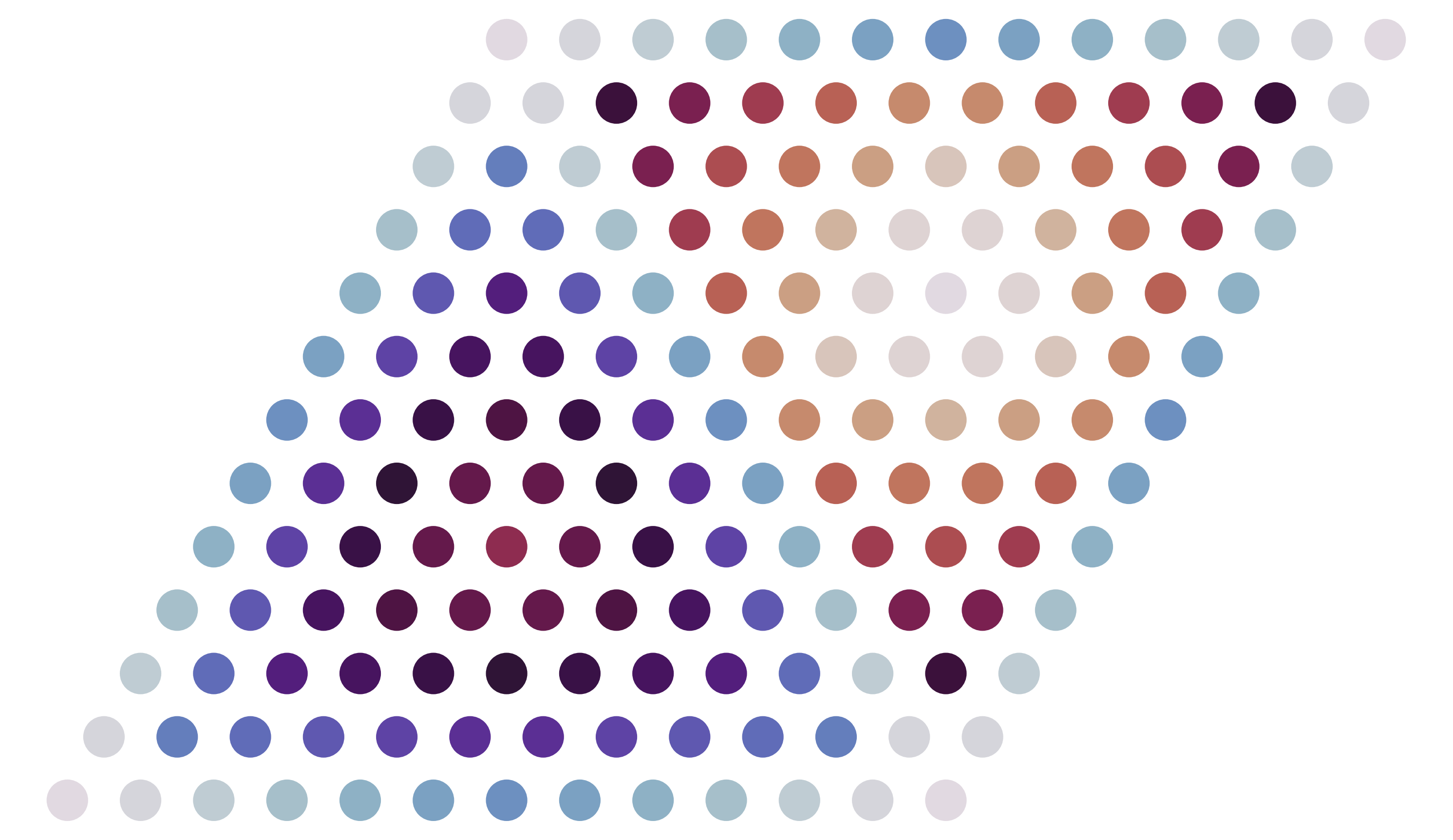 |
Different grid densities can greatly alter the number of slab orbits, which influence how many calculations you need to perform. Finding a "good" way to divide the grid can be especially tricky for lower symmetry unit cells. You can save a lot of calculation time by playing around with different grid divisions to find a ratio that bins your slabs into fewer orbits.